Solved Design a power factor correction circuit PFC to Circuit Diagram Basic Working. Now inside this IC we have many important building blocks. There's a voltage amplifier, then an analog multiplier and divider, a current amplifier and a PWM that runs at a fixed frequency. If we check the performance of this IC in a 250W power factor correction circuit, then we can see it has been properly tested using a
A SIMPLE explanation of Power Factor Correction (PFC). Learn what power factor correction is, why it is needed, and the formula & equation for power factor correction. Generally, it is used in power supply design for more than 100W. This type of power factor correction circuit consists of high-frequency switching elements like a diode, SCR

UC3854_Controlled_Power_Factor_Correction_Circuit_Design Circuit Diagram
Power Factor Versus DistortionPower Factor Versus Distortion Table 1 several sources: the feedforward signals, the feed-back loops, the output capacitor, the inductor and the input rectifiers. An active power factor corrector can easily achieve a high input power factor, usually much greater than 0.9. But power factor is not a sensitive meas-

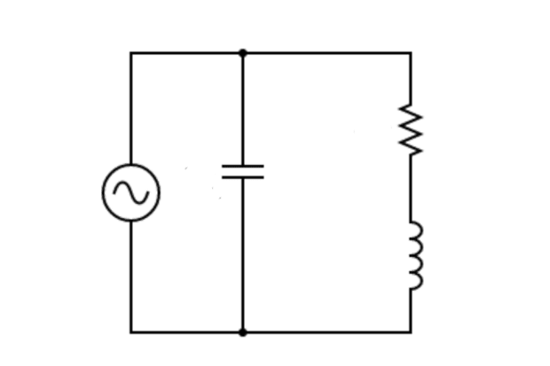
Power factor correction Power converters are required to present themselves as linear resistance to the supply voltage. If the input voltage, v, is a sine wave, so is the input current, i. + - v R i Linear resistor Technique: Power Factor Correction Power factor correction (PFC) basics. 00:09:09. Power factor correction (PFC) classification and control laws. 00:07:42. Power factor correction (PFC) topology comparison. 00:11:59. How to design an efficient power factor correction (PFC) circuit. 00:08:14. Power factor correction (PFC) design example. 00:07:22 What are a power factor and power factor correction? Many electronic circuits have a capacitor at the input of the power supply so as to operate with DC voltage. This capacitor might causes a phase shift between the sinusoidal AC power supply voltage and current and the power factor (PF) will drop. A power factor correction (PFC) circuit

Power Factor Correction (PFC) Circuit Circuit Diagram
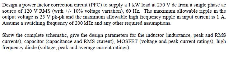
In this Power Factor Correction PFC tutorial, a basic PFC circuit and the calculations used to design the circuit will be demonstrated. A PFC circuit is required as the power factor in a system can be degraded. One of these reasons is due to reactive power, the other is due to harmonics generated by the load device.