
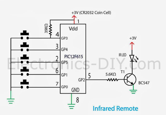
Infrared remote control switch circuit diagram How to make simple wireless remote control switch without relay, IR receiver remote control. ( CD4017 Remote control circuit, remote control light )Note: Thi
Construction of Remote Control ON-OFF Switch. To construct the remote control ON-OFF switch circuit, connect the CD4017 IC to power and ground, and connect the IR sensor output to the clock input of the IC. The outputs of the CD4017 IC should be connected to the base terminals of the BC547 transistors through appropriate resistors.

Simple wireless Remote control switch using TSOP 1738, IR ... Circuit Diagram
( IR sensor project )This is an IR receiver using a TSOP 1738. This is a v Simple wireless Remote control switch using TSOP 1738, IR Receiver Remote control.
Infrared Remote Control Circuit using IC 555 and Transistors. Here's a straightforward infrared switch designed for remote control purposes. It utilizes a typical IR LED and IR diode detector pair, specifically the CGIY89A/BPW50 components. Transmitter Circuit. The 555 IC based IR transmitter circuit generates a series of pulses to drive the IR
+.jpg)
How to Make Remote Control ON Circuit Diagram
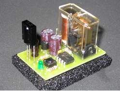
Point your IR remote control at the TSOP312 receiver module. Press any button on the remote control. You should see the relay click and its onboard LED will turn ON. Press the button again. The relay should click again, and the LED will turn OFF. Note that this circuit can be a bit sensitive to noise from other IR sources. An IR remote control (RC) switch is a simple electronic configuration used to attain dynamic control of AC/DC with the push of a button. IR remote control switches use IR rays to communicate with one another and allow the user to gain access to any place or object locked behind the said switch. With the current onset of the COVID-19 pandemic.
